Figure 1-2 Networking of the BSC in the CDMA2000 1X network

Figure 1-3 shows the networking of the BSC in the CDMA2000 1xEV-DO network.

Figure 1-4 shows the networking of the BSC in the digital trunking network.
Modular Design for Realizing Flexible Configuration
The BSC6600 uses a modular service-processing structure. Service modules and service boards can be flexibly configured to meet different capacity demands and ensure smooth expansion of the system, and the system reliability is also improved.
Customer-Oriented Design for Decreasing the CAPEX and OPEX
Though the increasing subscribers and services bring benefits to the operators when the equipment is in service, the increasing equipment also brings increasing CAPEX and OPEX to the operators. The BSC6600 is designed in large capacity to protect the effective investment of the operators. The large-capacity BSC6600 that uses IP transmission can support up to 20,000 Erl voice traffic or 1 Gbit/s data service traffic. If the TDM transmission is used, the voice traffic can reach 12,000 Erl.
The BSC6600 supports dynamic power amplifier control. When the system is idle, if the load on a sector is light, the system automatically powers off the carriers that adopts the assistant ARFCNs of the sector to reduce the power consumption and decrease the CAPEX and OPEX.
Dynamic Balance for Promoting Customers' Experience
The BSC6600 supports the 4th Generation Vocoders (4GV). The 4 GV can reduce the average data rate without decreasing the voice quality. In this way, the capacity is improved. The voice quality and the system capacity achieve the dynamic balance which brings maximum benefits to operators and promotes the customers' experience.
Support for the Ongoing Evolution of the CDMA2000 Network
In terms of design, the BSC allows for the ongoing evolution of the CDMA2000 technology and network. The CDMA2000 1X system can be smoothly upgraded through software to support CDMA2000 1xEV-DO services. The CDMA2000 1X/1xEV-DO network can be smoothly upgraded through software and new interface boards to support CDMA2000 1xEV-DO Rev A services.
Built-in Signaling Analyzer for Facilitating Tracing and Interpreting Messages
The BSC has a built-in signaling analyzer that traces and interprets all kinds of messages in the system to acquaint engineers with service processing details. It can trace and interpret the messages of the specified subscriber, interface, or protocol layer.
The graphical interface for message interpretation and the tracking review function enable engineers to acquaint and analyze entire processes of various services, and control the transmission processes and contents of subscriber signaling messages, interface signaling messages, and signaling messages of specified protocol layers. In this way, engineers can accurately locate and clear faults.
Performance Specifications
Table 5-1 shows the service processing capabilities of the BSC.
| Item
|
Specification
|
| Voice traffic
|
TDM transmission over the A interface:
Maximum voice traffic of the BSC: 12,000 Erl
Maximum voice traffic per subrack of the BSC: 750 Erl
|
IP transmission over the A interface:
Maximum voice traffic of the BSC: 20,000 Erl
Maximum voice traffic per subrack of the BSC: 1250 Erl
|
| Overall Busy Hour Call Attempts (BHCA)
|
2,880,000
180,000 (one subrack)
|
| Number of air interface channels
|
21,600 TCEs
|
| Number of E1/T1 ports over the A interface
|
512
|
| Number of FE ports over the A interface
|
64
|
| Number of E1/T1 ports over the Abis interface
|
512
|
| Number of FE ports over the Abis interface
|
64
|
| Transmission rate of the satellite links over the Abis interface
|
300 kbit/s (forward peak rate of DO services)
|
| Maximum number of CDMA2000 1X carriers
|
540 (40 TCEs/carrier)
3,072
192 (one subrack)
|
| Maximum number of CDMA2000 1xEV-DO carriers
|
1,920
192 (one subrack)
|
| Number of PPP connections for packet data services
|
350,000
|
| Number of PPP connections that can be simultaneously activated for packet data services
|
25,000
|
| Packet data throughput
|
1 Gbit/s
|
The specifications shown in Table 5-1 are the maximum values supported by the BSC in the CDMA2000 1X network and CDMA2000 1xEV-DO network.
The following is the reference traffic model.
| Item
|
Specification
|
| Average daily peak hour traffic intensity of mobile subscribers
|
0.025 Erl
|
| Average call duration of mobile subscribers
|
60s
|
| Average trunk traffic in busy hours
|
0.8 Erl
|
| Average call duration on trunks
|
60s
|
Table 5-2 lists the specifications of the Huawei CDMA digital trunking communication system.
| Item
|
Specification
|
| Maximum number of group calls a CIPS can simultaneously support
|
405
|
| Maximum number of group calls that a sector carrier can simultaneously support
|
40
|
| Maximum number of subscribers that a sector carrier can simultaneously support
|
200
|
| Maximum number of group call subscribers a CIPS can simultaneously support
|
810
|
| Maximum number of private calls a CIPS can simultaneously support
|
810
|
| Maximum number of group calls that a BSC can simultaneously support
|
2000
|
The following is the reference traffic model.
| Item
|
Specification
|
| Busy hour traffic
|
0.032 Erl
|
| Average call duration
|
30s (including 3s of channel reserve time)
|
Physical and Electrical Specifications
Table 5-3 shows the specifications of a fully-configured BSC.
| Item
|
Specification
|
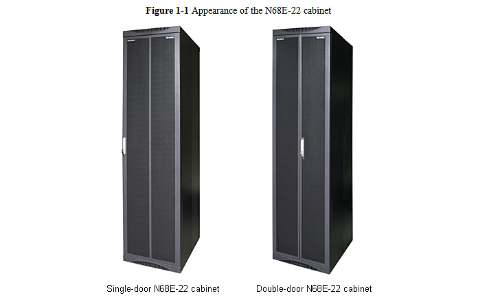
| Cabinet Type
|
N68E-22 cabinet
|
| Dimensions
|
Height: 2200 mm [86.61 in.]
Width: 600 mm [23.62 in.]
Depth: 800 mm [31.50 in.]
|
| Cabinet weight
|
Fully configured cabinet: ≤ 350 kg [771.75 lb]; Empty cabinet: ≤ 140 kg [308.7 lb]
|
| Number of cabinets in the full configuration
|
7
|
| Power input
|
-48 V DC (-40 V DC to -57 V DC)
|
| Power consumption of the entire cabinet
|
16600 W
|
| Lightning protection level
|
±4000V, 8/20 μs
|
Reliability Specifications
Table 5-4 lists the specifications of the BSC reliability.
| Item
|
Specification
|
| Availability
|
0.9999964
|
| Mean time between failures (MTBF)
|
140815.91 h
|
| Mean Time to repair (MTTR)
|
0.5 h
|
Clock Specifications
Table 5-5 lists the technical specifications of the clock subsystem of the BSC.
| Item
|
Specification
|
| Clock sources
|
Timing signals output by satellite receivers, external clock signals (2,048 kHz, 2,048 kbit/s, and 8 kHz), clock signals extracted from lines, and clock signals generated by the local crystal oscillator
|
| Working modes
|
Fast pull-in mode, tracing mode, holding mode, and free-run mode
|
| Clock signal stratums
|
Three stratums of clock signals
|
Environmental Specifications
Environmental requirements for the BSC cover the requirements for the storage, transportation, and running environment. The following standards must be complied with:
GB 4798 environmental conditions for electrician and electronic products application
ETS 300019 equipment engineering (EE); environmental conditions and environmental tests for telecommunications equipment
IEC 60721 classification of environmental conditions
Table 5-6 shows the climatic requirements for the equipment storage environment.
| Item
|
Storage Environment
|
Transportation Environment
|
Running Environment
|
| Temperature
|
-40oC to +70oC
|
-40oC to +70oC
|
Long term: 15OC to 30OC
|
| Short term: 0OC to 45OC
|
| Temperature change rate
|
≤ 1OC/min
|
≤ 3OC/min
|
≤ 3OC/min
|
| Relative Humidity
|
10% to 100%
|
5% to 100%
|
Long term: 40% to 75%
|
| Short term: 20% to 90%
|
| Altitude
|
≤ 5000 m
|
≤ 5000 m
|
≤ 4000 m
|
| Air pressure
|
70 kPa to 106 kPa
|
70 kPa to 106 kPa
|
70 kPa to 106 kPa
|
| Solar radiation
|
≤ 1120 W/m²
|
≤ 1120 W/m²
|
≤ 700 W/m²
|
| Thermal radiation
|
≤ 600 W/m²
|
≤ 600 W/m²
|
≤ 600 W/m²
|
| Wind speed
|
≤ 30m/s
|
≤ 30m/s
|
≤ 1 m/s
|