Solución de diseño y planificación de redes backhaul de puente WLAN de Huawei para implementaciones de videovigilancia
Debido a factores geográficos, los sitios de vigilancia como ciudades, campos petroleros y carreteras de alta velocidad se distribuyen de forma dispersa. Si se utilizan redes alámbricas para el backhaul de datos, se produce una gran cantidad de carga de trabajo. La función de backhaul inalámbrico de WLAN puede resolver este problema. Es difícil garantizar la calidad de backhaul porque la distancia de backhaul es larga. Una buena planificación y un buen diseño de red pueden garantizar la calidad de señales de backhaul y ancho de banda.
WLAN planning process:

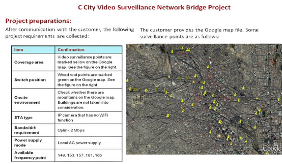
Demand Collection
Demand Type |
Description |
|---|---|
Terminal distribution |
Understand the size of the area where a terminal is distributed and the general situation of terminal distribution. |
Wired aggregation location |
Understand the location of wired-sized devices (access switches or optical fibers). Root APs must be connected the wired access network. |
Signal transmission environment |
Understand the major obstacles (tall buildings, mountains, and trees) in the area. Both sides of the bridge must be away from obvious obstacles. |
Terminal type |
Understand the type of terminals. In particular, understand whether a terminal has the Wi-Fi function. |
Bandwidth requirement |
Terminal's bandwidth requirement (usually, only upstream bandwidth is considered) |
Power supply mode |
Understand whether customers have clear requirements on the power supply mode and which types of power supply facilities and areas on the site are available. |
Available frequency point |
Understand what local 5 GHz channels are available. |
Site construction |
Understand whether there are clear requirements on construction of outdoor sites. For example, customers do not allow sites to be constructed on building roofs in the residential community. |
1. Detailed drawings (Google maps or outdoor drawings) of the coverage area are the basic requirement.
2. Different projects have different requirements. The preceding requirements are the basic requirements of most projects. If customers have any special requirements, the requirements must be taken into consideration separately.
Site Survey Information
Based on different scenarios and requirements, site surveys are classified into simple site surveys and detailed site surveys with consideration of the investment cost.
Simple site survey: Applicable to simple scenarios or some pre-sales projects that do not have detailed requirements on the solution.
Detailed site survey: Applicable to complex scenarios or post-sales network planning projects that have high requirements on the solution.
Planning and Design
Since different projects have different scenarios and requirements, there may be differences between the network planning solutions and focuses. Based on project support experience, planning of most of the bridge projects is not complicated. Product selection, backhaul links, bandwidth, and site design must be taken into consideration.

Product Selection
AP selection:
1. When the upstream distance is long, and optical interfaces must be used, select AP6610DN.
2. When only local AC power can be provided, select AP6610DN.
3. When PoE power is provided, select AP6510DN.
Backhaul link design:
1. Select the bridging mode:

2. Select the backhaul antenna:

Selection principles:
a) Aggregation APs and endpoint APs use antennas whose horizontal beam width is within 15°.
b) When the backhaul distance is within 2 km, select antennas whose gain is 18 dBi.
c) When the backhaul distance is between 2 km and 3 km, select antennas whose gain is 23 dBi.
d) When the backhaul distance is longer than 3 km, select antennas whose gain is 28 dBi.

Selection principles:
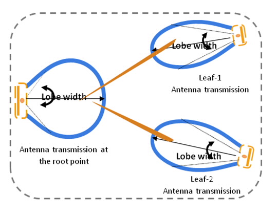
a) Antennas selected for the aggregation APs must cover all antennas of the endpoint APs. Antennas whose horizontal beam width is equal to or larger than 60° are recommended.
b) Select antennas whose horizontal beam width is with 15° for the endpoint APs.
c) When the backhaul distance is within 1 km, select antennas whose gain is 11 dBi for the aggregation APs.
d) When the backhaul distance is longer than 1 km, select antennas whose gain is 16 dBi for the aggregation APs.
e) Select antennas whose gain is 18 dBi for the endpoint APs when point-to-multipoint data transmission is used.
Bandwidth Design
1. Point-to-point data transmission
a) When the backhaul distance is with 2 km, select antennas whose gain is 18 dBi to ensure lossless bandwidth of backhaul links.
b) When the backhaul distance is between 2 km and 3 km, select antennas whose gain is 23 dBi to ensure lossless bandwidth of backhaul links.
c) When the backhaul distance is longer than 3 km, select antennas whose gain is 28 dBi to ensure lossless bandwidth of backhaul links.
2. Point-to-multipoint data transmission
a) When the backhaul distance is with 1 km, data from one point can be transmitted to a maximum of six points. In this manner, effective bandwidth of each endpoint AP is up to 4 Mbps.
b) When the backhaul distance is between 1 km and 3 km, it is recommended that data from one point be transmitted to a maximum of six points. In this manner, effective bandwidth of each endpoint AP is up to 4 Mbps.
c) When the backhaul distance is longer than 3 km, point-to-multipoint data transmission is not recommended.
Deployment Design
1. Site design
a) There must be no obstacle between the aggregation point and relay point, and the relay point and endpoint.
b) Reliable power must be provided for a site.
c) When the backhaul distance is longer than 3 km, select antennas whose gain is 28 dBi to ensure lossless bandwidth of backhaul links.
2. Cable layout and power supply
a) The length of cable from an AP to a switch must be within 90 m.
b) Approximately 5 m must be reserved for the network cable for subsequent adjustment.
c) Keep sites away from strong current and strong magnetic fields.
d) Make confirmations with customers in advance to avoid customers' disagreement on construction due to factors such as property and appearance.
3. Antenna deployment
a) Ensure that there is no obstacle between the aggregation point and endpoint as well as in the Fresnel zone.
b) Adjust the azimuth angle of the endpoint APs' antennas to make their main lobe directly face the aggregation point APs' antennas.
c) Adjust the azimuth angle of the aggregation point APs' antennas to make their main lobe cover all the endpoint APs' antennas.

4. Channel design
a) Make confirmations with customers that local channels are available.
b) Prevent co-channel interference

Scenario Introduction

Device Selection:
1. When AC power is provided onsite, select AP6610DN.
2. Select 18 dBi antennas during point-to-point data transmission and 11 dBi antennas during point-to-multipoint data transmission.
3. Antennas are temporarily selected and will be adjusted according to conditions such as the backhaul distance between sites and bandwidth design.
Backhaul Link Design:
1. Select the terminal connection mode and set endpoint APs:


2. Select the bridging mode and set relay APs and aggregation APs:

3. Select backhaul antennas and set relay APs and aggregation APs:

Bandwidth Design:
When the bridge is designed based on the three principles of backhaul link design, 2 Mbps bandwidth can be ensured for cameras. In some special scenarios, if the principles are not complied with, you need to calculate whether the terminal's bandwidth meets the standards through bandwidth design methods.
Site Design:
1. In urban areas, it is recommended that APs be installed against poles on the top of a building. APs and antennas are installed against poles to avoid blocking caused by tall buildings or mountains.
2. Use AC power supply on the top of a building.
3. Ensure that there is no obstacle between antennas and relay APs, and antennas and endpoint APs. Ensure that the antennas of the endpoint APs directly face the aggregation point APs. Ensure that antennas of the aggregation APs cover all the endpoint APs.
4. Aggregation APs or neighboring backhaul lines at the same site use non-overlapping channels (149, 153, 157, 161, and 165).
-
Productos & Soluciones
- Todos los Productos
- Todas las Soluciones
-
Cómo Comprar
- Contacto del Revendedor
- Publicar Sus Requisitos
-
Cómo ser un Partner
- Cómo Registrarse para Calificar como Partner
-
Participar en Cursos
- Consultar Certificados
- Consulta de Partners Autorizados para la Capacitación
- Academia Huawei en Línea
-
Sobre Huawei Empresa
- Quem somos
- O que fazemos
- Publicaciones
- Newsletters
Copyright © Huawei Technologies Co., Ltd. 1998-2017. All rights reserved.
Términos & Condiciones|Política de Privacidad|Mapa del sitio|Contacto Local TAC
