Controlador de acceso AC6005
El controlador de acceso (CA) AC6005 de Huawei ofrece redes empresariales pequeñas y medianas. Este AC de gran capacidad integra la funcionalidad switch Ethernet de 1000 M tanto para el control de acceso alámbrico como inalámbrico. El AC6005 entrega una solución de networking flexible fácil de instalar y mantener para redes de campus, y redes industriales y empresariales medianas.
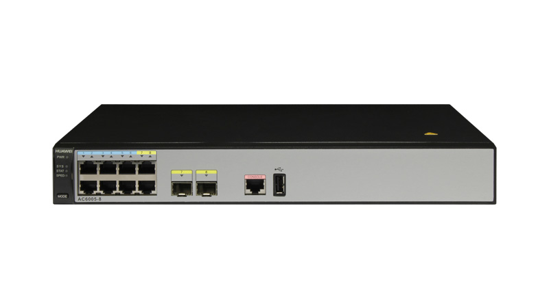
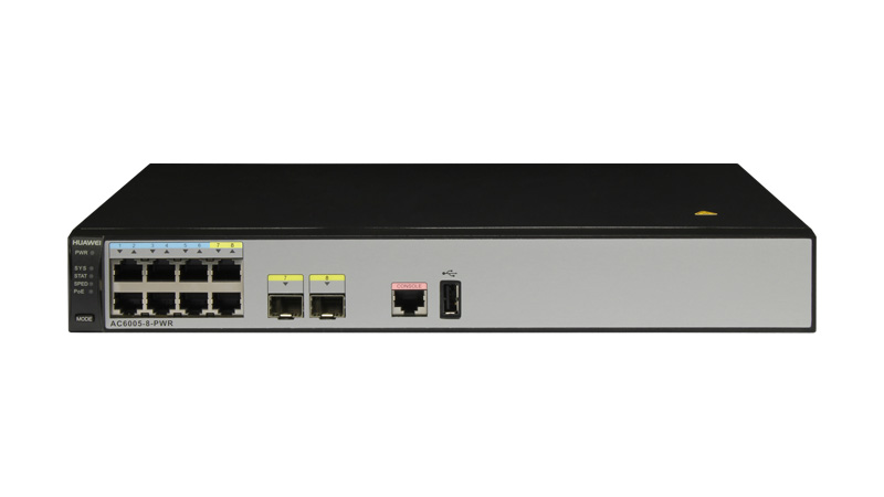
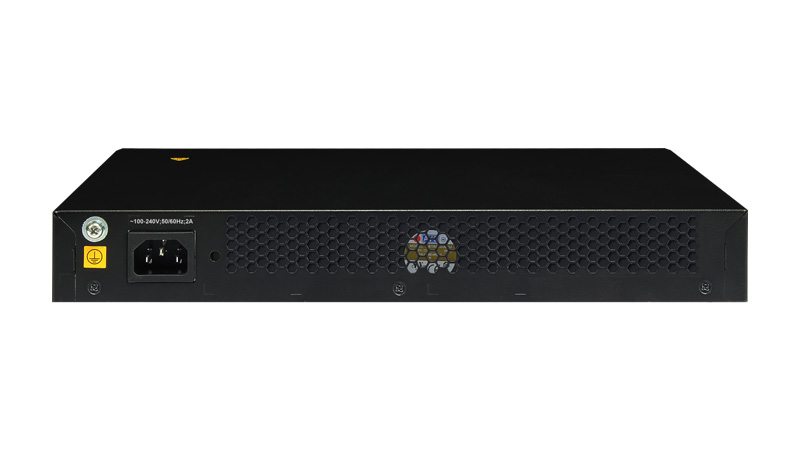
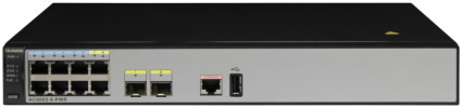
Appearance
Ports
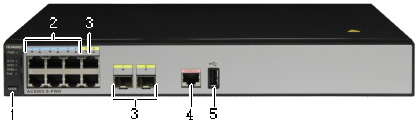
1. MODE button: switches working mode of indicators.
2. Six 10/100/1000BASE-T Ethernet electrical ports
3. Two combo ports
4. Console port
5. USB port
Indicator Description
The AC6005-8-PWR has the same indicators on the front panel as the AC6005-8 except that the AC6005-8-PWR has a PoE indicator. The following uses the appearance of the AC6005-8-PWR as an example.
| No. | Indicator/Button | Status | Description |
|---|---|---|---|
| 1 | Power supply indicator: PWR | Off | The AC6005-8-PWR is powered off. |
| Steady green | The power supply is working properly. | ||
| Steady orange NOTE:Only the PWR indicator on the AC6005-8-PWR displays orange. | The PoE power supply is faulty. | ||
| 2 | System status indicator: SYS | Off | The system is not running. |
| Green | Fast blinking: The system is starting. Slow blinking: The system is running properly. | ||
| Steady red | The system cannot start normally, or an overheat alarm or fan alarm is generated. | ||
| 3 | State mode indicator: STAT | Off | The state mode is not selected. |
| Steady green | The service port indicator works in the default mode (STAT). In this mode, the indicator indicates the port status. | ||
| 4 | Speed mode indicator: SPED | Off | The speed mode is not selected. |
| Steady green | The service port indicator indicates the port speed. After 45 seconds, the service port indicator automatically restores to the default mode (STAT). | ||
| 5 | PoE mode indicator: PoE NOTE:Only the AC6005-8-PWR has this indicator. |
Off | The PoE mode is not selected. |
| Steady green | The service port indicator indicates the PoE status of each port. After 45 seconds, the service port indicator automatically restores to the default mode (STAT). | ||
| 6 | Mode switching button: MODE | - | AC6005-8-PWR: When you press the button once, the SPED indicator turns green and the service port indicators indicate the speed of the ports. When you press the button for a second time, the PoE indicator turns green and the service port indicators indicate the PoE status of the ports. When you press the button for a third time, the STAT indicator turns green. AC6005-8: When you press the button once, the SPED indicator turns green and the service port indicators indicate the speed of the ports. When you press the button for a second time, the STAT indicator turns green. If you do not press the button within 45 seconds, the indicators restore to the default mode. That is, the STAT indicator turns green, and the SPED and PoE indicators are off. |
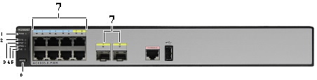
| 7 | Service port indicator
GE electrical ports: The first indicator indicates the status of the bottom left port. The indicators correspond to the ports from bottom to top and from left to right. GE optical ports: Each optical port has a corresponding indicator above it. |
Descriptions of service port indicators vary in different modes. For details, see the following table. | |
| Mode | Status | Description |
| STAT | Off | No link has been established to the port or the port has been shut down. |
| Green | Steady on: A link has been established to the port. Blinking: The port is sending or receiving data. | |
| SPED | Off | No link has been established to the port or the port has been shut down. |
| Green | Steady on: The port is working at 10 or 100 Mbit/s. Blinking: The port is working at 1000 Mbit/s. | |
| PoE NOTE:Only the AC6005-8-PWR has this indicator. |
Off | The port is not providing PoE power. |
| Steady green | The port is providing PoE power. | |
| Orange | Steady on: The PoE function is disabled on the port. Blinking: The port stops providing PoE power because a fault occurs, for example, an incompatible powered device (PD) is connected to the port. | |
| Blinking green and orange | The port cannot provide PoE power due to any of the following reasons: The power of the PD exceeds the power supply capability of the port or exceeds the threshold. The overall output power has reached the maximum output capability of the device. The PoE power function is not enabled on the interface in manual power-management mode. |
Abundant Port Types
- 8 GE Service ports
- One RJ45 maintenance serial port
- One USB Maintenance port.
Large Capacity, High Performance, Integrated Design
- Large forwarding capacity: the AC has 8 GE ports, and provides 4 Gbit/s forwarding capacity.
- PoE: The AC supports the PoE function and can provide the maximum power on 8 ports. This PoE capability can provide power to APs and other powered devices (PDs) connected to the AC unit.
Carrier-Class Reliability
- Port backup based on the Link Aggregation Control Protocol (LACP) or Multiple Spanning Tree Protocol (MSTP).
- The AC supports 1+1 hot backup.
Easy-to-Install and Easy-to-Maintain
- The AC6005 dimensions (width x depth x height) are 320 mm × 233.6 mm × 43.6 mm and the AC6005 can be installed on a desk or in a standard IEC cabinet(19 inch).
- The built-in web system of AC allows local GUI-based management.
- The AC can be managed by the eSight that provides various northbound interfaces.
- The AC supports the intra-board temperature probe, which monitors the operating environment of the AC in real time.
Energy Conservation
- Low noise fans that can adjust the speed automatically are used, thus reducing noises in the system and power consumption of fans.
- The chip switches to the power saving mode when no connected device is detected on a service interface, that is, the interface is idle.
- It uses highly-integrated and energy-saving chips produced through advanced processing techniques. With the help of the intelligent device management system, the chips not only improve system performance but also greatly reduce power consumption of the entire system.
Switching and forwarding features
| Feature | Description | |
|---|---|---|
| Ethernet features | Ethernet | Operating modes of full duplex, half duplex, and auto-negotiation Rates of an Ethernet interface: 10 Mbit/s, 100 Mbit/s, 1000 Mbit/s, and auto-negotiation Jumbo frames Link aggregation Load balancing among links of a trunk Interface isolation and forwarding restriction Broadcast storm suppression |
| VLAN | Access modes of access, trunk, and hybrid Default VLAN | |
| MAC | Automatic learning and aging of MAC addresses
Static, dynamic, and blackhole MAC address entries Packet filtering based on source MAC addresses Interface-based MAC learning limiting | |
| ARP | Static and dynamic ARP entries ARP in a VLAN Aging of ARP entries | |
| LLDP | LLDP | |
| Ethernet loop protection | MSTP | STP RSTP MSTP BPDU protection, root protection, and loop protection Partitioned STP |
IPv4 forwarding |
IPv4 features |
ARP and RARP |
| Unicast routing features | Static route RIP-1 and RIP-2 OSPF BGP IS-IS Routing policies and policy-based routing URPF check DHCP client, server and relay DHCP snooping | |
| Multicast routing features | IGMPv1, IGMPv2, and IGMPv3 PIM-SM Multicast routing policies RPF | |
IPv6 forwarding |
IPv6 features |
ND Protocol |
| Unicast routing features | Static route RIPng OSPFv3 BGP4+ IS-IS IPv6 DHCPv6 DHCPv6 Snooping | |
| Multicast routing features | MLD MLD Snooping | |
| Device reliability | BFD | BFD |
| Layer 2 multicast features | Layer 2 multicast | IGMP snooping Prompt leave Multicast traffic control Inter-VLAN multicast replication |
| Ethernet OAM | EFM OAM | Neighbor discovery Link monitoring Fault notification Remote loopback |
| QoS features | Traffic classification | Traffic classification based on the combination of the L2 protocol header, IP 5-tuple, outbound interface, and 802.1p priority |
| Action | Access control after traffic classification Traffic policing based on traffic classification Re-marking packets based on traffic classifiers Class-based packet queuing Associating traffic classifiers with traffic behaviors | |
| Queue scheduling | PQ scheduling DRR scheduling PQ+DRR scheduling WRR scheduling PQ+WRR scheduling | |
| Congestion avoidance | SRED WRED | |
| Configuration and maintenance | Terminal service | Configurations using command lines Error message and help information in English and Chinese Login through console and Telnet terminals Send function and data communications between terminal users |
| File system | File systems Directory and file management File uploading and downloading using FTP and TFTP | |
| Debugging and maintenance | Unified management over logs, alarms, and debugging information Electronic labels User operation logs Detailed debugging information for network fault diagnosis Network test tools such as traceroute and ping commands Interface mirroring and flow mirroring | |
| Version upgrade | Device software loading and online software loading BootROM online upgrade In-service patching | |
| Security and management | System security | Different user levels for commands, preventing unauthorized users from accessing AC6005 SSHv2.0 RADIUS and HWTACACS authentication for login users ACL filtering DHCP packet filtering (with the Option 82 field) Defense against control packet attacks Defenses against attacks such as source address spoofing, Land, SYN flood (TCP SYN), Smurf ping flood (ICMP echo), Teardrop, and Ping of Death attacks IPSec |
| Network management | ICMP-based ping and traceroute SNMPv1, SNMPv2c, and SNMPv3 Standard MIB RMON | |
AP Management Specifications
| Feature | Specifications |
|---|---|
| AP access control | Displays MAC addresses or SNs of APs in the whitelist.
Adds a single AP or multiple APs (by specifying a range of MAC addresses or SNs) to the whitelist. Automatically discovering and manually confirming APs. Automatically discovering APs without manually confirming them. |
| AP region management | Supports three AP region deployment modes: Distributed deployment: APs are deployed independently. An AP is equivalent to a region and does not interfere with other APs. APs work at the maximum power and do not perform radio calibration. Common deployment: APs are loosely deployed. The transmit power of each radio is less than 50% of the maximum transmit power. Centralized deployment: APs are densely deployed. The transmit power of each radio is less than 25% of the maximum transmit power. Specifies the default region to which automatically discovered APs are added. |
| AP profile management | Specifies the default AP profile that is applied to automatically discovered APs. |
| AP type management | Manages AP attributes including the number of interfaces, AP types, number of radios, radio types, maximum number of virtual access points (VAPs), maximum number of associated users, and radio gain (for APs deployed indoors). Provides default AP types. Supports user-defined AP types. |
| Network topology management | Supports LLDP topology detection. |
Radio Management Specifications
| Feature | Specifications |
|---|---|
Radio profile management |
The following parameters can be configured in a radio profile: Radio working mode and rate |
| Unified static configuration of parameters | Radio parameters such as the channel and power of each radio are configured on the AC and then delivered to APs. |
| Dynamic management | APs can automatically select working channels and power when they go online. In an AP region, APs automatically adjust working channels and power in the event of signal interference: Global calibration: The optimal working channel and power of a specified AP can be adjusted. Partial calibration: The optimal working channels and power of all the APs in a specified region can be adjusted. When an AP is removed or goes offline, the AC6005 increases the power of neighboring APs to compensate for the coverage hole. Automatic selection and calibration of radio parameters in AP regions are supported. |
Enhanced service capabilities |
The AC supports 802.1a/b/g/n/ac. These modes can be used independently or jointly (a\n, b\g, b\g\n, and g\n). |
WLAN Service Management Specifications
| Feature | Specifications |
|---|---|
| ESS management | Allows you to enable SSID broadcast, set the maximum number of access users, and set the association aging time in an ESS. Isolates APs at Layer 2 in an ESS. Maps an ESS to a service VLAN. Associates an ESS with a security profile or a QoS profile. Enables IGMP for APs in an ESS. |
| VAP-based service management | Adds multiple VAPs at a time by binding radios to ESSs. Displays information about a single VAP, VAPs with a specified ESS, or all VAPs. Supports configuration of offline APs. Creates VAPs according to batch delivered service provisioning rules in automatic AP discovery mode. |
| Service provisioning management | Supports service provisioning rules configured for a specified radio of a specified AP type. Adds automatically discovered APs to the default AP region. The default AP region is configurable. Applies a service provisioning rule to a region to enable APs in the region to go online. |
| Multicast service management | Supports IGMP snooping. Supports IGMP proxy. |
| Load balancing | Performs load balancing among radios in a load balancing group. Supports two load balancing modes: Based on the number of STAs connected to each radio Based on the traffic volume on each radio |
QOS
WLAN Security Specifications
| Feature | Specifications |
|---|---|
| WLAN security profile management | Manages authentication and encryption modes using WLAN security profiles. Binds security profiles to ESS profiles. |
| Authentication modes | Open system authentication with no encryption WEP authentication/encryption WPA/WPA2 authentication and encryption: WPA/WPA2-PSK+TKIP WPA/WPA2-PSK+CCMP WPA/WPA2-802.1x+TKIP WPA/WPA2-802.1x+CCMP WAPI authentication and encryption: Supports centralized WAPI authentication. Supports three-certificate WAPI authentication, which is compatible with traditional two-certificate authentication. Issues a certificate file together with a private key. Allows users to use MAC addresses as accounts for authentication by the RADIUS server. Portal authentication: Allows an AC to function as a portal gateway. Prohibits an AC from functioning as a portal gateway. Supports only Layer 2 portal. |
| Combined authentication | Combined MAC authentication: PSK+MAC authentication MAC+portal authentication: MAC authentication is used first. When MAC authentication fails, portal authentication is used. This type of authentication applies only to centralized forwarding. |
| AAA | Local authentication/local accounts (MAC addresses and accounts) RADIUS authentication Multiple authentication servers: Supports backup authentication servers. Specifies authentication servers based on account. Configures authentication servers based on account. Binds user accounts to SSIDs. |
| Security isolation | Port-based isolation User group-based isolation |
| WIDS | Rouge device scan, identification, defense, and countermeasures, which includes dynamic blacklist configuration and detection of rogue APs, STAs, and network attacks. |
| Authority control | ACL limit based on the following: Port User group User |
| Other security features | SSID hiding IP source guard: Configures IP and MAC binding entries statically. Generates IP and MAC binding entries dynamically. |
WLAN user management specifications
Management and Maintenance Features
Physical Specifications
| Item | Description | |
|---|---|---|
| Dimensions (width x depth x height) | 320 mm×233.6 mm×43.6 mm | |
| Maximum power consumption | AC6005-8-PWR: 163.6 W (device power consumption: 39.6 W, PoE: 124 W) AC6005-8: 25.6 W | |
| Weight | AC6005-8-PWR: 2.30 kg AC6005-8: 2.05 kg | |
| Operating temperature | -5ºC to +50ºC | |
| Relative humidity | 5% RH to 95% RH, non-condensing | |
| Operating altitude | -60 m to 5000 m | |
| AC input voltage | Rated voltage | 100 V AC to 240 V AC, 50/60 Hz |
| Voltage range | 90 V AC to 264 V AC, 47 Hz to 63 Hz | |
System Configuration
| Item | Specifications |
|---|---|
| Processor | Dominant frequency: 1 GHz |
| Switching capacity | 20 Gbit/s |
| Forwarding capacity | 4 Gbit/s |
| DDR memory | 2 GB |
| Flash memory | 2 GB (SD card) |
Protocol and Management Capabilities
| Parameter | Specifications |
|---|---|
| Number of managed APs | 128 |
| Number of access users | Entire device: 2K Single AP: a maximum of 256 (depending on the AP model) |
| Number of MAC address entries | 4K |
| Number of VLANs | 4K |
| Number of routing entries | 4K |
| Number of multicast forwarding entries | 4K |
| Number of DHCP IP address pools | 4K |
| Number of local users | 128 IP address pools, each of which contains a maximum of 16K IP addresses |
| Number of ACLs | 1000 |
| Number of ESSIDs | 4K |
| User group management | 1K |
Wireless Networking Capabilities
| Feature | Specifications |
|---|---|
| Networking between APs and ACs | APs and ACs can be connected through a Layer 2 or Layer 3 network.
APs can be directly connected to an AC. APs are deployed on a private network, while ACs are deployed on the public network to implement NAT traversal. ACs can be used for Layer 2 bridge forwarding or Layer 3 routing. |
| Forwarding mode | Direct forwarding (distributed forwarding or local forwarding) Tunnel forwarding (centralized forwarding) Centralized authentication and distributed forwarding Before users are authenticated, tunnel forwarding is used. After users are authenticated, local forwarding is used. |
| Wireless networking mode | WDS bridging: Point-to-point (P2P) wireless bridging Point-to-multipoint (P2MP) wireless bridging Automatic topology detection and loop prevention (STP) Wireless mesh network: Access authentication for mesh devices Mesh routing algorithm Go-online without configuration |
AC discovery |
An AP can obtain the device's IP address in any of the following ways: Static configuration |
CAPWAP tunnel |
Centralized CAPWAP |
Active and standby ACs |
Enables and disables the switchback function. |
Application Scenarios
The AC is connected to an aggregation switch in chain or branched mode.
The AC processes both control flows and data flows. Management flows must be transmitted over Control And Provisioning of Wireless Access Points (CAPWAP) tunnels. Data flows can be transmitted over CAPWAP tunnels or not, as required.
The CAPWAP protocol defines how APs communicate with ACs and provides a general encapsulation and transmission mechanism for communication between APs and ACs. CAPWAP defines data tunnels and control tunnels.
Data tunnels encapsulate 802.3 data packets to be sent to the AC.
Control tunnels transmit control flows for remote AP configuration and WLAN management.
Two forwarding modes are available according to whether data flows are transmitted on CAPWAP tunnels:
Direct forwarding: is also called local or distributed forwarding.
Tunnel forwarding: is also called centralized forwarding. It is usually used to control wireless user traffic in a centralized manner.
You can select the chain or branched mode according to networking requirements. On the AC, you can configure direct forwarding for some APs and tunnel forwarding for other APs. In tunnel forwarding mode, all wireless user traffic is aggregated to an AC, which may create a switching bottleneck. Therefore, tunnel forwarding is seldom used on enterprise networks.
In bypass networking mode, the AC is connected to a network device (usually an aggregation switch) to manage APs.
The AC manages APs. Management flows are transmitted in CAPWAP tunnels, and data flows are forwarded to the upper layer network by the aggregation switch and do not pass through the AC.
Inline Networking
In inline networking mode, APs or access switches are directly connected to the AC. The AC functions as both an AC and an aggregation switch to forward and process APs' data and management services.
In inline networking mode, the AC sets up CAPWAP tunnels with APs to configure and manage these APs over CAPWAP tunnels. Service data of wireless users can be forwarded between APs and the AC over CAPWAP data tunnels or be directly forwarded by APs.
In inline networking mode, direct forwarding is often used so that user service data can be forwarded on APs.
The AC functions as the DHCP server to allocate IP addresses to APs. APs obtain the IP address of the AC using the DNS function, DHCP Option 43 or DHCP Option 15 in DHCP packets, or Layer 2 discovery protocols, and set up data tunnels with the AC.
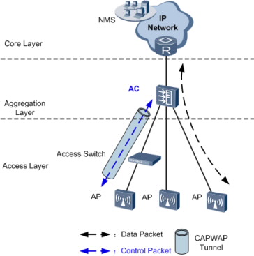
In direct forwarding mode, only control flows are transmitted in CAPWAP tunnels, and data flows sent from APs are transparently transmitted to the upstream device by the AC, as shown in Figure.Data flows are identified by VLAN IDs.
When data flows are not transmitted in CAPWAP tunnels, configure management VLANs and data VLANs as follows:
On the AC and its upstream devices, configure an AC management VLAN to transmit control flows between the AC and the NMS.
On the switches between APs and the AC, configure AP management VLANs to transmit control flows between APs and the AC.
On all switches between APs and the AC, configure data VLANs to differentiate WLAN service flows.
The AC provides powerful access, aggregation, and switching capabilities. In addition, the AC provides PoE or PoE+ power. Therefore, APs can directly connect to the AC. Direct forwarding is often used in inline networking mode. This networking mode simplifies the network architecture and applies to medium- and small-scale and centralized WLANs.
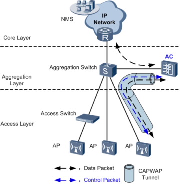
Bypass Networking
In bypass networking mode, the AC is connected to a network device (usually an aggregation switch) to manage APs.
The AC manages APs. Management flows are transmitted in CAPWAP tunnels, and data flows are forwarded to the upper layer network by the aggregation switch and do not pass through the AC.
Tunnel Forwarding
In tunnel forwarding mode, wireless user service data is transmitted between APs and ACs over CAPWAP tunnels.
In Figure, both management flows and data flows of APs are transmitted to the AC over CAPWAP tunnels, and then the AC transparently transmits these flows to the upstream device.
Tunnel forwarding is usually used to control wireless user traffic in a centralized manner. This forwarding mode facilitates device deployment and controls all wireless user data flows by aggregating traffic of all wireless users connected to APs to an AC through CAPWAP data tunnels.
Direct Forwarding
In direct forwarding mode, wireless user service data is translated from 802.3 packets into 802.11 packets, which are then forwarded by an uplink aggregation switch.
The bypass networking mode is often used on enterprise networks. Wireless user service data does not need to be processed by an AC, eliminating the bandwidth bottleneck and facilitating the usage of existing security policies. Therefore, this networking mode is recommended for integrated network deployment.
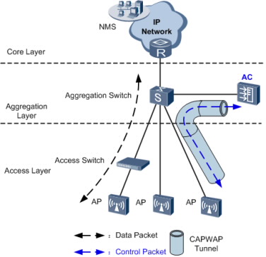
The AC only manages APs. All AP control flows must reach the AC.
Interfaces connected to the AC are reserved on the aggregation switch. The aggregation switch functions as the DHCP server to allocate IP addresses to APs. APs obtain the IP address of the AC using the DNS function, DHCP Option 43 or DHCP Option 15 in DHCP packets.
Data flows from APs are forwarded by the Layer 2 switch and aggregation switch, and do not pass through the AC.
Different service VLANs are assigned to STAs with different service set identifiers (SSIDs). The access switch and aggregation switch identify packets from these VLANs and forward these packets to the upstream device. The aggregation switch controls user access, and allocates IP addresses to users. After a user is authenticated by the aggregation switch, traffic from the user is forwarded to the Internet across the IP network.
Wireless Backhaul Networking
The 802.11 wireless technology has been widely used in home networks and enterprise networks. Users can easily access the Internet over WLANs. In this network application, APs must be connected to the existing wired network to provide network access services for wireless users. To expand the wireless coverage area, APs need to be connected using cables, switches, and power supplies. This increases network costs and prolongs network construction period. Wired deployment requirements may not be met in special circumstances. The Wireless Distribution System (WDS) or Wireless Mesh Network allows APs to be connected wirelessly, facilitating WLAN construction in a complex environment.
WDS
The WDS is a distribution system comprised of APs. The WDS connects to an AC on the network side, which is then connected to a network device such as a gateway or an aggregation switch. The WDS connects to a station (STA) or PC on the user side.
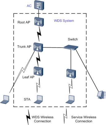
On a WDS network, an AC manages the following devices:
Root AP: connects to an AC on the wired side, and functions as a WDS master to connect to trunk APs or leaf APs.
Trunk AP: functions as a WDS slave to connect to a root AP, connects to wired devices on the wired side, or functions as a WDS master to connect to leaf APs.
Leaf AP: functions as a WDS slave to connect to a root AP or trunk AP or connects to STAs on the wireless side.
The WDS networking can expand WLANs and applies to indoor wireless deployment scenarios.
Wireless Mesh Network
Compared with a traditional WLAN, a wireless mesh network (WMN) has the following advantages:
Fast deployment: Mesh nodes can be easily installed to construct a WMN in a short time, much shorter than the construction period of a traditional WLAN.
Dynamic coverage area expansion: As more mesh nodes are deployed on a WMN, the WMN coverage area can be rapidly expanded.
Robustness: A WMN is a peer-to-peer network that will not be affected by the failure of a single node. If a node fails, packets are forwarded to the destination node along other paths.
Flexible networking: An AP can join or leave a WMN easily, allowing for flexible networking.
Various application scenarios: Besides traditional WLAN scenarios such as enterprise networks, office networks, and campus networks, a WMN also applies to scenarios such as large-scale warehouses, docks, MANs, metro lines, and emergency communications.
Cost-effectiveness: Only MPPs need to connect to a wired network, which minimizes the dependency of a WMN on wired devices and saves costs in wired device purchasing and cable deployment.
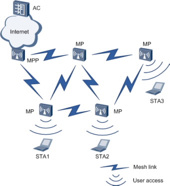
Nodes on a WMN can be classified into the following types based on their functions:
Mesh point (MP)
A mesh-capable node that uses IEEE 802.11 MAC and physical layer protocols for wireless communication. This node supports automatic topology discovery, automatic route discovery, and data packet forwarding.
Mesh portal point (MPP)
An MP that connects to a WMN or another type of network. This node has the portal function and enables mesh nodes to communicate with external networks.
On a WMN, MPs are fully meshed to establish an auto-configured, and self-healing backbone WMN, and MPPs with the gateway function provide connections to the Internet. An MP provides access services and connects a terminal to a WMN. A WMN uses special mesh routing protocols, which ensures high transmission quality. The WMN is applicable to scenarios that require high-bandwidth and highly-stable Internet connections.
Dual-AC Networking
To ensure uninterrupted service forwarding, enterprises that require high reliability use active and standby ACs for networking.
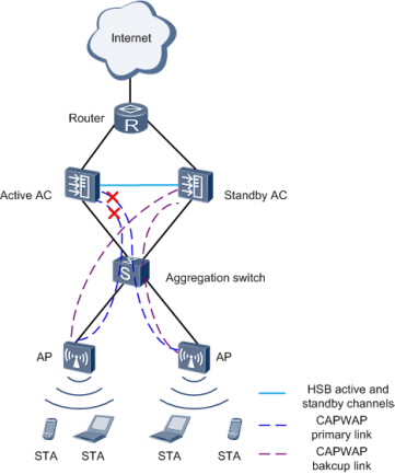
Dual-AC backup can be implemented in two modes:
HSB + dual-link backup: as shown in Figure an AP establishes CAPWAP tunnels with both the active and standby ACs. The two ACs synchronize service information (such as NAC and WLAN service information) through the hot standby (HSB) function. When an AP is disconnected from the active AC, the AP notifies the standby AC of a switchover.
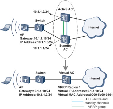
HSB + VRRP: as shown in Figure an AP obtains only the virtual IP address of both the active and standby ACs. The active AC backs up information including AP entries, CAPWAP link information, and user information on the standby AC. In this mode, the AP only detects the presence of one AC. The active/standby switchover is determined by the Virtual Router Redundancy Protocol (VRRP). Currently, this mode cannot be used in a VRRP multi-instance scenario.
-
Productos & Soluciones
- Todos los Productos
- Todas las Soluciones
-
Cómo Comprar
- Contacto del Revendedor
- Publicar Sus Requisitos
-
Cómo ser un Partner
- Cómo Registrarse para Calificar como Partner
-
Participar en Cursos
- Consultar Certificados
- Consulta de Partners Autorizados para la Capacitación
- Academia Huawei en Línea
-
Sobre Huawei Empresa
- Quem somos
- O que fazemos
- Publicaciones
- Newsletters
Copyright © Huawei Technologies Co., Ltd. 1998-2017. All rights reserved.
Términos & Condiciones|Política de Privacidad|Mapa del sitio|Contacto Local TAC