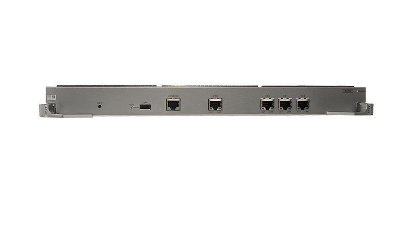
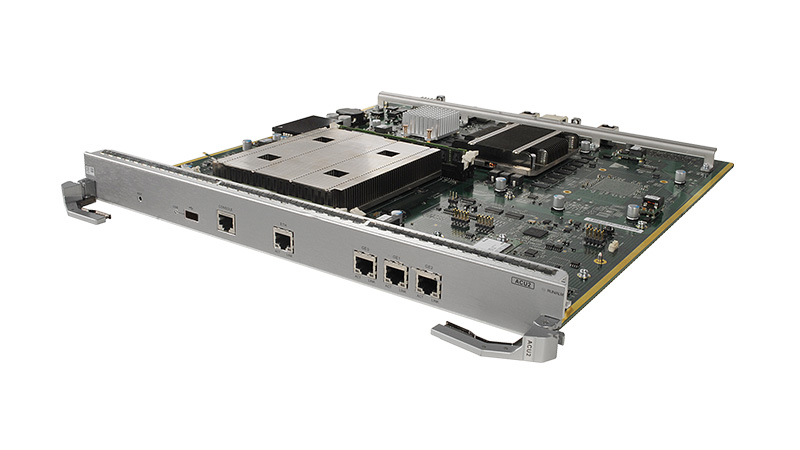
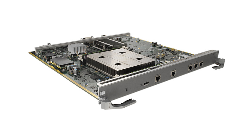
Unidad del controlador de acceso ACU2
La unidad 2 del controlador de acceso de Huawei es una unidad de servicios de valor agregado utilizada en un switch de chasis y proporciona capacidades de control de acceso en redes WLAN de grandes empresas. Un switch de chasis con un ACU2 dispone de capacidades de servicio inalámbricas y alámbricas. Esto reduce el espacio ocupado y los cables en las salas de equipos, y disminuye el costo de construcción de red.
• Capacidad de transmisión de 40 Gbit/s.
• 2048 puntos de acceso.
• 32 000 usuarios.
• Redundancia inmediata 1+1.
Appearance
Ports

| No. | Interface | Quantity | Description |
|---|---|---|---|
| 1 | USB interface | 1 | Connects to a USB flash drive to transfer configuration files. |
| 2 | Console interface | 1 | Provides a serial interface. To configure the ACU2 locally, you can log in to the local ACU2 by connecting a cable between the serial interface on the host and the console interface on the ACU2. |
| 3 | Ethernet interface | 1 | Provides a GE interface. To configure the ACU2, you can log in to the ACU2 through Telnet. |
| 4 | GE interface | 3 | Reserved interface |
Indicator Description

| No. | Indicator/Button | Color | Description |
|---|---|---|---|
| 1 | RST | - | The Reset button is used for resetting cards manually. Resetting a card interrupts services. Confirm the action before you press this button. |
| 2 | USB | Off | In the current version, the USB indicator remains off. |
| 3 | ACT | Amber | When the indicator blinks, data is being transmitted or received. When the indicator is off, no data is being transmitted or received. |
| 4 | LINK | Green-yellow | When the indicator is on, the link is connected. When the indicator is off, the link is blocked. |
| 5 | RUN/ALM | Green | When the indicator is on, the board is powered on but the software is not running. When the indicator blinks once every 2s (0.5 Hz), the system is running properly. When the indicator blinks once every 0.25s (4 Hz), the system is starting. |
| Red | When the indicator is on, the board is faulty. | ||
| Orange | When the indicator is on, the board is installed in the slot and is powered on. |
High access capacity and processing capability
- An ACU2 can manage a maximum of 2048 APs (packet forwarding over 2048 tunnels) and supports a maximum of 32K STAs.
- The ACU2 provides nearly 40 Gbit/s line-speed forwarding capacity.
Independent service unit, facilitating centralized deployment and capacity expansion
- The ACU2 provides access control capabilities on an enterprise wireless network. An aggregation switch with ACU2s provides both wireless and wired service capabilities, reducing space occupied and cables in equipment rooms and lowering network construction cost.
- You can install multiple ACU2s on a switch to manage Nx2048 APs. (N is the number of ACU2s.)
Flexible user policy management and authority control capabilities
- The ACU2 implements per-user access control based on ACLs, VLAN IDs, and bandwidth limits sent from the RADIUS server.
- You can define user groups for users of different rules and apply access control policies to the user groups. Access of users in a user group is controlled based on the ACL, user isolation policy, and bandwidth limit applied to the user group. You can configure inter-group user isolation or intra-group user isolation as required to implement access control.
Visualized WLAN network management and maintenance
- The ACU2 and APs establish a fit AP+AC networking for centralized AP management, facilitating network management and maintenance. Huawei AC and AP products support standard Link Layer Discovery Protocol (LLDP), which helps display topology of wired and wireless networks for visualized management and maintenance.
Switching and forwarding features
| Feature | Description | |
|---|---|---|
| Ethernet features | Ethernet | Jumbo frames Link aggregation Load balancing among links of a trunk Interface isolation and forwarding restriction Broadcast storm suppression |
| VLAN | Access modes of access, trunk, and hybrid Default VLAN | |
| MAC | Automatic learning and aging of MAC addresses Static, dynamic, and blackhole MAC address entries Packet filtering based on source MAC addresses Interface-based MAC learning limiting | |
| ARP | Static and dynamic ARP entries ARP in a VLAN Aging of ARP entries | |
| LLDP | LLDP | |
| Ethernet loop protection | MSTP | STP RSTP MSTP BPDU protection, root protection, and loop protection Partitioned STP |
| IPv4 forwarding | IPv4 features | ARP and RARP ARP proxy Auto-detection NAT |
| Unicast routing features | Static route RIP-1 and RIP-2 OSPF BGP IS-IS Routing policies and policy-based routing URPF check DHCP client, server and relay DHCP snooping | |
| Multicast routing features | IGMPv1, IGMPv2, and IGMPv3 PIM-SM Multicast routing policies RPF | |
| IPv6 forwarding | IPv6 features | ND Protocol |
| Unicast routing features | Static route RIPng OSPFv3 BGP4+ IS-IS IPv6 DHCPv6 DHCPv6 Snooping | |
| Multicast routing features | MLD | |
| Device reliability | BFD | BFD |
| Layer 2 multicast features | Layer 2 multicast | IGMP snooping Prompt leave Multicast traffic control Inter-VLAN multicast replication |
| Ethernet OAM | EFM OAM | Neighbor discovery Link monitoring Fault notification Remote loopback |
| QoS features | Traffic classification | Traffic classification based on the combination of the L2 protocol header, IP 5-tuple, and 802.1p priority |
| Action | Access control after traffic classification Traffic policing based on traffic classification Re-marking packets based on traffic classifiers Class-based packet queuing Associating traffic classifiers with traffic behaviors | |
| Queue scheduling | PQ scheduling DRR scheduling PQ+DRR scheduling WRR scheduling PQ+WRR scheduling | |
| Congestion avoidance | SRED WRED | |
| Configuration and maintenance | Terminal service | Configurations using command lines Error message and help information in English Configurations using Web Platform Login through console and Telnet terminals Send function and data communications between terminal users |
| File system | File systems Directory and file management File uploading and downloading using FTP and TFTP | |
| Debugging and maintenance | Unified management over logs, alarms, and debugging information Electronic labels User operation logs Detailed debugging information for network fault diagnosis Network test tools such as traceroute and ping commands Interface mirroring and flow mirroring | |
| Version upgrade | Device software loading and online software loading BootROM online upgrade In-service patching | |
| Security and management | System security | Different user levels for commands, preventing unauthorized users from accessing device SSHv2.0 RADIUS and HWTACACS authentication for login users ACL filtering DHCP packet filtering (with the Option 82 field) Defense against control packet attacks Defenses against attacks such as source address spoofing, Land, SYN flood (TCP SYN), Smurf, ping flood (ICMP echo), Teardrop, and Ping of Death attacks IPSec |
| Network management | ICMP-based ping and traceroute SNMPv1, SNMPv2c, and SNMPv3 Standard MIB RMON | |
AP Management Specifications
Feature |
Description |
|---|---|
AP access control |
Displays MAC addresses or SNs of APs in the whitelist. |
AP region management |
Supports three AP region deployment modes: |
AP profile management |
Specifies the default AP profile that is applied to automatically discovered APs. |
AP type management |
Manages AP attributes including the number of interfaces, AP types, number of radios, radio types, maximum number of virtual access points (VAPs), maximum number of associated users, and radio gain (for APs deployed indoors). |
Network topology management |
Supports LLDP topology detection. |
Radio Management Specifications
Feature |
Description |
|---|---|
Radio profile management |
The following parameters can be configured in a radio profile: |
Unified static configuration of parameters |
Radio parameters such as the channel and power of each radio are configured on the AC and then delivered to APs. |
Dynamic management |
APs can automatically select working channels and power when they go online. |
Enhanced service capabilities |
The AC supports 802.1a/b/g/n/ac. These modes can be used independently or jointly (a\n, b\g, b\g\n, and g\n). |
WLAN Service Management Specifications
Feature |
Description |
|---|---|
ESS management |
Allows you to enable SSID broadcast, set the maximum number of access users, and set the association aging time in an ESS. Isolates APs at Layer 2 in an ESS. Maps an ESS to a service VLAN. Associates an ESS with a security profile or a QoS profile. Enables IGMP for APs in an ESS. |
VAP-based service management |
Adds multiple VAPs at a time by binding radios to ESSs. Displays information about a single VAP, VAPs with a specified ESS, or all VAPs. Supports configuration of offline APs. Creates VAPs according to batch delivered service provisioning rules in automatic AP discovery mode. |
Service provisioning management |
Supports service provisioning rules configured for a specified radio of a specified AP type. Adds automatically discovered APs to the default AP region. The default AP region is configurable. Applies a service provisioning rule to a region to enable APs in the region to go online. |
Multicast service management |
Supports IGMP snooping. Supports IGMP proxy. |
Load balancing |
Performs load balancing among radios in a load balancing group. Supports two load balancing modes: Based on the number of STAs connected to each radio Based on the traffic volume on each radio |
BYOD (Bring Your Own Device) |
Identification of device types according to the OUI in the MAC address Identification of device types according to the user agent (UA) field in an HTTP packet Identification of device types according to DHCP Option information Carrying of device type information in RADIUS authentication and accounting packets |
Positioning services |
Locating AeroScout and Ekahau tags Locating Wi-Fi terminals |
Spectrum analysis |
Identification of the following interference sources: bluetooth, microwave ovens, cordless phones, ZigBee, game controller, 2.4 GHz/5 GHz wireless audio and video devices, and baby monitors. Working with the eSight to locate the interference sources and display spectrum. |
QOS
Feature |
Description |
|---|---|
WMM profile management |
Enables or disables Wi-Fi Multimedia (WMM). Allows a WMM profile to be applied to radios of multiple APs. |
Traffic profile management |
Manages traffic from APs and maps packet priorities according to traffic profiles. Applies a QoS policy to each ESS by binding a traffic profile to each ESS. |
AC traffic control |
Manages QoS profiles. Uses ACLs to perform traffic classification. Limits the incoming traffic rate on each physical port based on inbound CAR parameters and limits the outgoing traffic rate based on outbound CAR or traffic shaping parameters. Limits incoming and outgoing traffic rates for each user based on inbound and outbound CAR parameters. Limits the traffic rate based on ESSs or VAPs. |
AP traffic control |
Controls traffic of multiple users and allows users to share bandwidth. Limits the rate of a specified VAP. |
Packet priority configuration |
Sets the QoS priority (IP precedence or DSCP priority) for CAPWAP control channels. Sets the QoS priority for CAPWAP data channels: Allows you to specify the CAPWAP header priority. Maps 802.1p priorities of user packets to ToS priorities of tunnel packets. |
Airtime scheduling |
Allocates equal time to users for occupying the channel, which improves users' Internet access experience. |
WLAN Security Specifications
Feature |
Description |
|---|---|
WLAN security profile management |
Manages authentication and encryption modes using WLAN security profiles. Binds security profiles to ESS profiles. |
Authentication modes |
Open system authentication with no encryption WEP authentication/encryption WPA/WPA2 authentication and encryption: WPA/WPA2-PSK+TKIP WPA/WPA2-PSK+CCMP WPA/WPA2-802.1x+TKIP WPA/WPA2-802.1x+CCMP WAPI authentication and encryption: Supports centralized WAPI authentication. Supports three-certificate WAPI authentication, which is compatible with traditional two-certificate authentication. Issues a certificate file together with a private key. Allows users to use MAC addresses as accounts for authentication by the RADIUS server. Portal authentication: Allows an AC to function as a portal gateway. Prohibits an AC from functioning as a portal gateway. Supports only Layer 2 portal. |
Combined authentication |
Combined MAC authentication: PSK+MAC authentication MAC+portal authentication: MAC authentication is used first. When MAC authentication fails, portal authentication is used. This type of authentication applies only to centralized forwarding. |
AAA |
Local authentication/local accounts (MAC addresses and accounts) RADIUS authentication Multiple authentication servers: Supports backup authentication servers. Specifies authentication servers based on account. Configures authentication servers based on account. Binds user accounts to SSIDs. |
Security isolation |
Port-based isolation User group-based isolation |
WIDS |
Rouge device scan, identification, defense, and countermeasures, which includes dynamic blacklist configuration and detection of rogue APs, STAs, and network attacks. |
Authority control |
ACL limit based on the following: Port User group User |
Other security features |
SSID hiding IP source guard: Configures IP and MAC binding entries statically. Generates IP and MAC binding entries dynamically. |
WLAN user management specifications
Feature |
Description |
|---|---|
Address allocation of wireless users |
Functions as a DHCP server to assign IP addresses to wireless users. |
WLAN user management |
Supports user blacklist and whitelist. Controls the number of access users: Based on APs Based on SSIDs Logs out users in any of the following ways: Using RADIUS DM messages Using commands Supports various methods to view information: Allows you to view the user status by specifying the user MAC address, AP ID, radio ID, or WLAN ID. Displays the number of online users in an ESS, AP, or radio. Collects packet statistics on air interface based on user. |
WLAN user roaming |
Supports intra-AC Layer 2 roaming. NOTE Users can roam between APs connected to different physical ports on an AC. Supports inter-VLAN Layer 3 roaming on an AC. Supports roaming between ACs. Supports fast key negotiation in 802.1x authentication. Authenticates users who request to reassociate with the AC and rejects the requests of unauthorized users. Delays clearing user information after a user goes offline so that the user can rapidly go online again. |
User group management |
Supports ACLs. Supports user isolation: Inter-group isolation Intra-group isolation |
Physical Specifications
| Item | Description |
|---|---|
| Board dimensions | 35.56 mm x 380.00 mm x 378.45 mm (height x width x depth) |
| Maximum power consumption | 168 W |
| Board weight | 3.2 kg |
System Configuration
| Item | Specifications |
|---|---|
Processor |
Two multi-core CPUs. Each CPU is configured with 16 cores. The dominant frequency is 600 MHz. |
DDR2 DRAM |
16 GB (8 bit, 2 x 4 GB). Each CPU is connected to a 8-GB memory. |
Flash |
64 MB |
NAND FLASH |
512 MB |
Forwarding capability |
40 Gbit/s |
Protocol and Management Capabilities
| Parameter | Specifications |
|---|---|
| Number of managed APs | 2K |
| Number of access users | Entire device: 32K Single AP: a maximum of 256 (depending on the AP model) |
| Number of MAC address entries | 32K |
| Number of VLANs | 4K |
| Number of routing entries | 16K |
Number of ARP entries |
32K |
| Number of multicast forwarding entries | 2K |
| Number of DHCP IP address pools | 256 IP address pools, each of which contains a maximum of 16K IP addresses |
| Number of local users | 1000 |
| Number of ACLs | 32K |
| Number of ESSIDs | 8K |
| User group management | 128 user groups Each user group can reference a maximum of eight ACLs. Each user group can associate with a maximum of 128 ACL rules. |
Wireless Networking Capabilities
Feature |
Specifications |
|---|---|
Networking between APs and ACs |
APs and ACs can be connected through a Layer 2 or Layer 3 network. APs can be directly connected to an AC. APs are deployed on a private network, while ACs are deployed on the public network to implement NAT traversal. ACs can be used for Layer 2 bridge forwarding or Layer 3 routing. |
Forwarding mode |
Direct forwarding (distributed forwarding or local forwarding) Tunnel forwarding (centralized forwarding) Centralized authentication and distributed forwarding Before users are authenticated, tunnel forwarding is used. After users are authenticated, local forwarding is used. |
Wireless networking mode |
WDS bridging: Point-to-point (P2P) wireless bridging Point-to-multipoint (P2MP) wireless bridging Automatic topology detection and loop prevention (STP) Wireless mesh network Access authentication for mesh devices Mesh routing algorithm Go-online without configuration |
AC discovery |
An AP can obtain the device's IP address in any of the following ways: Static configuration DHCP DNS The AC uses DHCP or DHCPv6 to allocate IP addresses to APs. DHCP or DHCPv6 relay is supported. On a Layer 2 network, APs can discover the AC by sending broadcast CAPWAP packets. |
CAPWAP tunnel |
Centralized CAPWAP CAPWAP control tunnel and data tunnel (optional) CAPWAP tunnel forwarding and direct forwarding in an extended service set (ESS) Datagram Transport Layer Security (DTLS) encryption, which is enabled by default for the CAPWAP control tunnel Heartbeat detection and tunnel reconnection |
Active and standby ACs |
Enables and disables the switchback function. Supports load balancing. Supports 1+1 hot backup. Supports N+1 backup. |
Application Scenarios
The ACU2 is connected to an aggregation switch in chain or branched mode.
The ACU2 processes both control flows and data flows. Management flows must be transmitted over Control And Provisioning of Wireless Access Points (CAPWAP) tunnels. Data flows can be transmitted over CAPWAP tunnels or not, as required.
The CAPWAP protocol defines how APs communicate with ACs and provides a general encapsulation and transmission mechanism for communication between APs and ACs. CAPWAP defines data tunnels and control tunnels.
Data tunnels encapsulate 802.11 data packets to be sent to the AC.
Control tunnels transmit control flows for remote AP configuration and WLAN management.
Two forwarding modes are available according to whether data flows are transmitted on CAPWAP tunnels:
Direct forwarding: is also called local or distributed forwarding.
Tunnel forwarding: is also called centralized forwarding. It is usually used to control wireless user traffic in a centralized manner.
Typical Networking of the ACU2
Deployment of the ACU2 in a WLAN (AC + fit AP) networking:
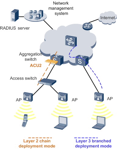
Different from an individual case-shaped AC, the ACU2 is installed on a switch. The ACU2 supports two deployment modes:
Layer 2 chain deployment mode: as shown above in the left part of Figure
The ACU2 is installed on an aggregation switch to manage APs connected to the aggregation switch directly or through an access switch.
In this deployment mode, the network between aggregation switches (ACs) and APs is a Layer 2 network.
Layer 3 branched deployment mode, as shown above in the right part of Figure
The ACU2 is installed on an aggregation switch other than the aggregation switch connected to APs. APs communicate with the ACU2 through the local aggregation switch. In this deployment mode, the network between ACs and APs is a Layer 3 network.
ACU2Forwarding Mode
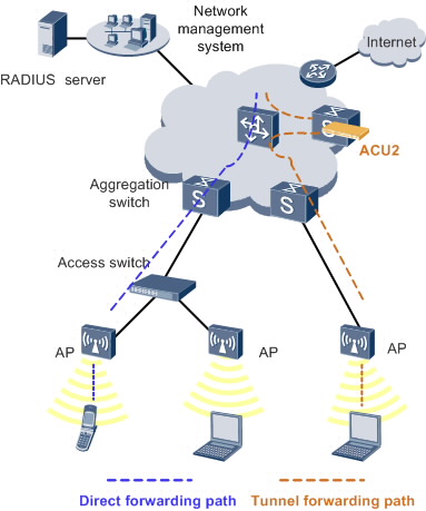
Direct Forwarding
In direct forwarding mode, wireless user service data is translated from 802.3 packets into 802.11 packets, which are then forwarded by an uplink aggregation switch.
The branched networking mode is often used on enterprise networks. Wireless user service data does not need to be processed by an AC, eliminating the bandwidth bottleneck and facilitating the usage of existing security policies. Therefore, this networking mode is recommended.
Tunnel Forwarding
In tunnel forwarding mode, wireless user service data is transmitted between APs and ACs over CAPWAP tunnels.
Both control flows and service data flows are transmitted in CAPWAP tunnels. APs send data packets to the switch where the ACU2 is installed, and the ACU2 decapsulates the packets and forwards the packets.
Traffic from wireless users under all APs is aggregated to the AC through CAPWAP tunnels to implement centralized traffic control.

