


AC6605 Access Controller
Huawei AC6605 is an access controller (AC) applicable to MANs and enterprise networks for wireless access. It has a large capacity and high performance. It is highly reliable, easy to install and maintain, and features advantages such as flexible networking and energy conservation.
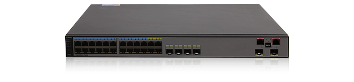
Abundant Port Types
- Uplink port :Two 10GE optical ports.
- Service port: 24 GE ports, the last four are used with four optical ports as combo interfaces.
- Maintenance port:One RJ45 maintenance serial port; One RJ45 maintenance Ethernet port ; One mini USB maintenance serial port.
Large Capacity, High Performance, Integrated Design
- Integrated design: An AC6605 device integrates the AC and LSW units to provide wireless access and wired access/aggregation services.
- Large switching capacity: An AC6605 device has 24 GE ports and 2 10GE ports, and provides 128 Gbit/s switching capacity.
- PoE: The AC6605 supports the PoE function and can provide the maximum power on 24 ports. This PoE capability can provide power to APs and other powered devices (PDs) connected to the AC unit.
Carrier-Class Reliability
- Port backup based on the Link Aggregation Control Protocol (LACP) or Multiple Spanning Tree Protocol (MSTP).
- Redundant AC/DC power supplies.
- Hot swappable power supplies.
Easy-to-Install and Easy-to-Maintain
- The AC6605 dimensions (width x depth x height) are 442 mm × 420 mm × 44.4 mm and the AC6605 can be installed in a standard cabinet.
- Power supplies are hot swappable, facilitating maintenance.
- The AC6605 can be managed by the eSight that provides various northbound interfaces.
- The AC6605 supports the Boolean port for environmental monitoring and the intra-board temperature probe, which monitors the operating environment of the AC6605 in real time.
Energy Conservation
- Low noise fans that can adjust the speed automatically are used, thus reducing noises in the system and power consumption of fans.
- The chip switches to the power saving mode when no connected device is detected on a service interface, that is, the interface is idle.
- It uses highly-integrated and energy-saving chips produced through advanced processing techniques. With the help of the intelligent device management system, the chips not only improve system performance but also greatly reduce power consumption of the entire system.
LSW Features and Specifications
| Feature | Description | |
|---|---|---|
| Ethernet features | Ethernet | Operating modes of full duplex, half duplex, and auto-negotiation Rates of an Ethernet interface: 10 Mbit/s, 100 Mbit/s, 1000 Mbit/s, and auto-negotiation Flow control on interfaces Jumbo frames Link aggregation Load balancing among links of a trunk Interface isolation and forwarding restriction Broadcast storm suppression |
| VLAN | Access modes of access, trunk, hybrid, and QinQ Default VLAN VLAN mapping Selective QinQ Voice VLAN | |
| MAC | Automatic learning and aging of MAC addresses Static, dynamic, and blackhole MAC address entries Packet filtering based on source MAC addresses Interface-based MAC learning limiting | |
| ARP | Static and dynamic ARP entries ARP in a VLAN Aging of ARP entries | |
| Smart Link | Smart Link Smart Link multi-instance Monitor Link | |
| LLDP | LLDP | |
| Ethernet loop protection | MSTP | STP RSTP MSTP BPDU protection, root protection, and loop protection Partitioned STP and BPDU tunnels |
| RRPP | RRPP protective switchover Single RRPP ring, tangent RRPP ring, and intersecting RRPP ring Hybrid networking of RRPP rings and other ring networks | |
| IPv4/IPv6 forwarding | IPv4 features | ARP and RARP ARP proxy Auto-detection |
| Unicast routing features | Static route RIP-1 and RIP-2 OSPF BGP IS-IS Routing policies and policy-based routing URPF check VRF DHCP client,server and relay DHCP snooping | |
| Multicast routing features | IGMPv1, IGMPv2, and IGMPv3 PIM-SM Multicast routing policies RPF | |
| IPv6 features | IPv6 protocol stack IPv6 unicast routing protocols: RIPng and OSPFv3 VRRP6 IPv4/IPv6 transition technologies | |
| Device reliability | BFD | Basic BFD functions BFD for OSPF BFD for IS-IS BFD for BGP BFD FOR PIM |
| Others | VRRP | |
| Layer 2 multicast features | Layer 2 multicast | IGMP snooping Prompt leave Multicast traffic control Inter-VLAN multicast replication Controllable multicast |
| Ethernet OAM | EFM OAM | Neighbor discovery Link monitoring Fault notification Remote loopback |
| CFM OAM | CCM check MAC ping MAC trace | |
| Y.1731 | Delay and variation measurement | |
| QoS features | Traffic classification | Traffic classification based on the combination of the L2 protocol header, IP 5-tuple, outbound interface, and 802.1p priority Traffic classification based on the C-VID and C-PRI of QinQ packets |
| Action | Access control after traffic classification Traffic policing based on traffic classification Re-marking packets based on traffic classifiers Class-based packet queuing Associating traffic classifiers with traffic behaviors | |
| Queue scheduling | PQ scheduling DRR scheduling PQ+DRR scheduling WRR scheduling PQ+WRR scheduling | |
| Congestion avoidance | SRED WRED | |
| Rate limiting on outbound interfaces | Rate limiting on outbound interfaces | |
| Configuration and maintenance | Terminal service | Configurations using command lines Error message and help information in English and Chinese Login through console and Telnet terminals Send function and data communications between terminal users |
| File system | File systems Directory and file management File uploading and downloading using FTP and TFTP | |
| Debugging and maintenance | Unified management over logs, alarms, and debugging information Electronic labels User operation logs Detailed debugging information for network fault diagnosis Network test tools such as traceroute and ping commands Interface mirroring and flow mirroring | |
| Version upgrade | Device software loading and online software loading BootROM online upgrade In-service patching | |
| Security and management | System security | Different user levels for commands, preventing unauthorized users from accessing AC6605 SSHv2.0 RADIUS and HWTACACS authentication for login users ACL filtering DHCP packet filtering (with the Option 82 field) Defense against control packet attacks Defenses against attacks such as source address spoofing, Land, SYN flood (TCP SYN), Smurf, ping flood (ICMP echo), Teardrop, and Ping of Death attacks |
| Network management | ICMP-based ping and traceroute SNMPv1, SNMPv2c, and SNMPv3 Standard MIBRMON | |
AC Features and Specifications
AP Management Specifications
| Feature | Specifications |
|---|---|
| AP access control | Displays MAC addresses or SNs of APs in the whitelist. Adds a single AP or multiple APs (by specifying a range of MAC addresses or SNs) to the whitelist. Automatically discovering and manually confirming APs. Automatically discovering APs without manually confirming them. |
| AP region management | Supports three AP region deployment modes: Distributed deployment: APs are deployed independently. An AP is equivalent to a region and does not interfere with other APs. APs work at the maximum power and do not perform radio calibration. Common deployment: APs are loosely deployed. The transmit power of each radio is less than 50% of the maximum transmit power. Centralized deployment: APs are densely deployed. The transmit power of each radio is less than 25% of the maximum transmit power. Specifies the default region to which automatically discovered APs are added. Supports a maximum of 256 AP regions with a region description of 63 characters. |
| AP profile management | Specifies the default AP profile that is applied to automatically discovered APs. Supports a maximum of 256 AP profiles. |
| AP type management | Manages AP attributes including the number of interfaces, AP types, number of radios, radio types, maximum number of virtual access points (VAPs), maximum number of associated users, and radio gain (for APs deployed indoors). Provides default AP types. Supports user-defined AP types. Supports a maximum of 256 AP types. |
| Network topology management | Supports LLDP topology detection. |
Radio Management Specifications
| Feature | Specifications |
|---|---|
| Radio profile management | The following parameters can be configured in a radio profile: Radio working mode and rate Automatic or manual channel and power adjustment mode Radio calibration interval The radio type can be set to 802.11n, 802.11b/g/n, or 802.11a/n. You can bind a radio to a specified radio profile. A maximum of 1024 radio profiles are supported. |
| Unified static configuration of parameters | Radio parameters such as the channel and power of each radio are configured on the AC and then delivered to APs. |
| Dynamic management | APs can automatically select working channels and power when they go online. In an AP region, APs automatically adjust working channels and power in the event of signal interference: Global calibration: The optimal working channel and power of a specified AP can be adjusted. Partial calibration: The optimal working channels and power of all the APs in a specified region can be adjusted. When an AP is removed or goes offline, the AC6605 increases the power of neighboring APs to compensate for the coverage hole. Automatic selection and calibration of radio parameters in AP regions are supported. |
| Enhanced service capabilities | The AC6605 supports 802.1a/b/g/n. These modes can be used independently or jointly (a/n, b/g, b/g/n, and g/n). That is, a total of eight modes can be used. The AC6605 preferentially uses the 5 GHz frequency band for STAs. |
WLAN Service Management Specifications
| Feature | Specifications |
|---|---|
| ESS management | Allows you to enable SSID broadcast, set the maximum number of access users, and set the association aging time in an ESS. Isolates APs at Layer 2 in an ESS. Maps an ESS to a service VLAN. Associates an ESS with a security profile or a QoS profile. Enables IGMP for APs in an ESS. Configures a maximum of 1024 ESSs. |
| VAP-based service management | Adds multiple VAPs at a time by binding radios to ESSs. Displays information about a single VAP, VAPs with a specified ESS, or all VAPs. Supports configuration of offline APs. Creates VAPs according to batch delivered service provisioning rules in automatic AP discovery mode. Supports up to 20000 VAPs. |
| Service provisioning management | Supports service provisioning rules configured for a specified radio of a specified AP type. Adds automatically discovered APs to the default AP region. The default AP region is configurable. Applies a service provisioning rule to a region to enable APs in the region to go online. Supports a maximum of 256 service provisioning rules. |
| Multicast service management | Supports IGMP snooping. Supports IGMP proxy. |
| Load balancing | Performs load balancing among radios in a load balancing group. Supports two load balancing modes: Based on the number of STAs connected to each radio Based on the traffic volume on each radio |
QOS
| Feature | Specifications |
|---|---|
| WMM profile management | Enables or disables Wi-Fi Multimedia (WMM). Supports a maximum of 32 WMM profiles. Allows a WMM profile to be applied to radios of multiple APs. |
| Traffic profile management | Manages traffic from APs and maps packet priorities according to traffic profiles. Supports a maximum of 32 traffic profiles. Applies a QoS policy to each ESS by binding a traffic profile to each ESS. |
| AC traffic control | Manages QoS profiles. Uses ACLs to perform traffic classification. Limits the incoming traffic rate on each physical port based on inbound CAR parameters and limits the outgoing traffic rate based on outbound CAR or traffic shaping parameters. Limits incoming and outgoing traffic rates for each user based on inbound and outbound CAR parameters. Limits the traffic rate based on ESSs or VAPs. |
| AP traffic control | Controls traffic of multiple users and allows users to share bandwidth. Limits the rate of a specified VAP. |
| Packet priority configuration | Sets the QoS priority (IP precedence or DSCP priority) for CAPWAP control channels. Sets the QoS priority for CAPWAP data channels: Allows you to specify the CAPWAP header priority. Maps 802.1p priorities of user packets to ToS priorities of tunnel packets. |
WLAN Security Specifications
| Feature | Specifications |
|---|---|
| WLAN security profile management | Manages authentication and encryption modes using WLAN security profiles. Binds security profiles to ESS profiles. Supports a maximum of 256 AP profiles. |
| Authentication modes | Open system authentication with no encryption WEP authentication/encryption WPA/WPA2 authentication and encryption: WPA/WPA2-PSK+TKIP WPA/WPA2-PSK+CCMP WPA/WPA2-802.1x+TKIP WPA/WPA2-802.1x+CCMP WAPI authentication and encryption: Supports centralized WAPI authentication. Supports three-certificate WAPI authentication, which is compatible with traditional two-certificate authentication. Issues a certificate file together with a private key. Allows users to use MAC addresses as accounts for authentication by the RADIUS server. Portal authentication: Allows an AC to function as a portal gateway. Prohibits an AC from functioning as a portal gateway. Supports only Layer 2 portal. |
| Combined authentication | Combined MAC authentication: PSK+MAC authentication MAC+portal authentication: MAC authentication is used first. When MAC authentication fails, portal authentication is used. This type of authentication applies only to centralized forwarding. |
| AAA | Local authentication/local accounts (MAC addresses and accounts) RADIUS authentication Multiple authentication servers: Supports backup authentication servers. Specifies authentication servers based on account. Configures authentication servers based on account. Binds user accounts to SSIDs. |
| Security isolation | Port-based isolation User group-based isolation |
| Authority control | ACL limit based on the following: Port User group User |
| Other security features | SSID hiding IP source guard: Configures IP and MAC binding entries statically. Generates IP and MAC binding entries dynamically. |
WLAN user management specifications
Management and Maintenance Features
| Type | Feature |
|---|---|
| Management | Debugging through the serial port or Ethernet port |
| Remote configuration using Telnet | |
| Device configuration using the CLI | |
| Device management using the U2560 | |
| System log | |
| Alarms with different severities | |
| Maintenance | Debugging information output |
| Ping | |
| Remote maintenance using SSH or Telnet | |
| Version management | Providing three methods to load version files to APs: Save the version files on APs. Send version files to APs through the control tunnels. Transfer version files to APs using FTP. |
| Checking and configuring mappings between AP types and version files so that APs can download version files automatically | |
| Manually downloading version files to APs of a specified type in batches and querying the download result |
Physical Specifications
| Item | Description | |
|---|---|---|
| Dimensions (width x depth x height) | 442 mm x 420 mm x 44.4 mm | |
| Maximum power consumption | 85 W | |
| Weight | Net weight: 5.48 kg Fully configured with 150 W power supplies: 7.16 kg Fully configured with 500 W power supplies: 7.48 kg | |
| Operating temperature | -5ºC to +50ºC | |
| Relative humidity | 5% RH to 95% RH, non-condensing | |
| Operating altitude | 150 W DC power supply: 0 m to 2000 m Others: 0 m to 3000 m | |
| AC input voltage | Rated voltage | 100 V AC to 240 V AC, 50/60 Hz |
| Voltage range | 90 V AC to 264 V AC, 47/63 Hz | |
| DC input voltage | Rated voltage | -48 V DC to -60 V DC |
| Voltage range | -36 V DC to -72 V DC | |
System Configuration
Protocol and Management Capabilities
Perform Specifications
| Feature | Specifications |
|---|---|
| Number of MAC addresses | 32 K for an LSW and 16 K for an AC |
| Number of VLANs | 4K |
| Number of ARP entries | 16 K for an LSW and 8 K for an AC |
| Number of routing entries | 12 K for an LSW and 8 K for an AC |
| Number of multicast forwarding entries | 2 K for an LSW and 4 K for an AC |
| Number of DHCP IP address pools | On an LSW: 128 IP address pools, each of which contains a maximum of 8 K IP addresses On an AC: 128 IP address pools, each of which contains a maximum of 16 K IP addresses |
Wireless Networking Capabilities
| Feature | Specifications |
|---|---|
| Networking between APs and ACs | APs and ACs can be connected through a Layer 2 or Layer 3 network. APs can be directly connected to an AC and powered by a 24-port PoE switch. ACs can function as both access and aggregation switches. APs are deployed on a private network, while ACs are deployed on the public network to implement NAT traversal. ACs can be used for Layer 2 bridge forwarding or Layer 3 routing. |
| Forwarding mode | Direct forwarding (distributed forwarding or local forwarding) Tunnel forwarding (centralized forwarding) Centralized authentication and distributed forwarding Before users are authenticated, tunnel forwarding is used. After users are authenticated, local forwarding is used. |
| Wireless networking mode | WDS bridging: Point-to-point (P2P) wireless bridging Point-to-multipoint (P2MP) wireless bridging Automatic topology detection and loop prevention (STP) |
| AC discovery | An AP can obtain the AC6605's IP address in any of the following ways: Static configuration DHCP Option 43 DNS The AC6605 uses DHCP to allocate IP addresses to APs. Huawei APs are identified by the Option 60 field. DHCP relay is supported. On a Layer 2 network, APs can discover the AC6605 by sending broadcast or multicast CAPWAP packets. |
| CAPWAP tunnel | Centralized CAPWAP CAPWAP control tunnel and data tunnel (optional). CAPWAP tunnel forwarding and direct forwarding in an extended service set (ESS). Datagram Transport Layer Security (DTLS) encryption, which is enabled by default for the CAPWAP control tunnel Heartbeat detection and tunnel reconnection. |
| Active and standby ACs | Enables and disables the switchback function. Supports load balancing. Supports 1+1, N+1, and N+N backup. |
Application Scenarios
The AC6605 is connected to an aggregation switch in chain or branched mode.
The AC6605 processes both control flows and data flows. Management flows must be transmitted over Control And Provisioning of Wireless Access Points (CAPWAP) tunnels. Data flows can be transmitted over CAPWAP tunnels or not, as required.
The CAPWAP protocol defines how APs communicate with ACs and provides a general encapsulation and transmission mechanism for communication between APs and ACs. CAPWAP defines data tunnels and control tunnels.
Data tunnels encapsulate 802.11 data packets to be sent to the AC6605.
Control tunnels transmit control flows for remote AP configuration and WLAN management.
Two forwarding modes are available according to whether data flows are transmitted on CAPWAP tunnels:
Direct forwarding: is also called local or distributed forwarding.
Tunnel forwarding: is also called centralized forwarding. It is usually used to control wireless user traffic in a centralized manner.
You can select the chain or branched mode according to networking requirements. On the AC6605, you can configure direct forwarding for some APs and tunnel forwarding for other APs. In tunnel forwarding mode, all wireless user traffic is aggregated to an AC, which may create a switching bottleneck. Therefore, tunnel forwarding is seldom used on enterprise networks.
Chain Networking
In chain networking mode, APs or access switches are directly connected to the AC6605. The AC6605 functions as both an AC and an aggregation switch to forward and process APs' data and management services.
In chain networking mode, the AC6605 sets up CAPWAP tunnels with APs to configure and manage these APs over CAPWAP tunnels. Service data of wireless users can be forwarded between APs and the AC6605 over CAPWAP data tunnels or be directly forwarded by APs.
In chain networking mode, direct forwarding is often used so that user service data can be forwarded on APs.
The AC6605 functions as the DHCP server to allocate IP addresses to APs. APs obtain the IP address of the AC6605 using the DNS function, DHCP Option 43 in DHCP packets, or Layer 2 discovery protocols, and then set up data tunnels with the AC6605.
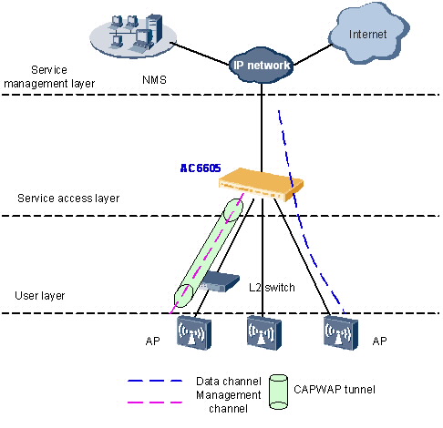
In direct forwarding mode, only control flows are transmitted in CAPWAP tunnels, and data flows sent from APs are transparently transmitted to the upstream device by the AC6605, as shown in Figure.Data flows are identified by VLAN IDs.
When data flows are not transmitted in CAPWAP tunnels, configure management VLANs and data VLANs as follows:
On the AC6605 and its upstream switches, configure an AC management VLAN to transmit control flows between the AC6605 and the NMS.
On the switches between APs and the AC6605, configure AP management VLANs to transmit control flows between APs and the AC6605.
On all switches between APs and the BRAS, configure data VLANs to differentiate WLAN service flows.
The AC6605 has a wired switching unit that provides powerful access, aggregation, and switching capabilities. In addition, the AC6605 provides PoE+ power for 24 interfaces so that APs can directly connect to the AC6605. Direct forwarding is often used in chain networking mode. This networking mode simplifies the network architecture and applies to large-scale and centralized WLANs.
Branched Networking
In branched networking mode, the AC6605 is connected to a network device (usually an aggregation switch) to manage APs.
The AC6605 only manages APs. Management flows are transmitted in CAPWAP tunnels, and data flows are forwarded to the upper layer network by the aggregation switch and BRAS and do not pass through the AC6605.
Direct Forwarding
In direct forwarding mode, wireless user service data is translated from 802.3 packets into 802.11 packets, which are then forwarded by an uplink aggregation switch.
The branched networking mode is often used on enterprise networks. Wireless user service data does not need to be processed by an AC, eliminating the bandwidth bottleneck and facilitating the usage of existing security policies. Therefore, this networking mode is recommended.
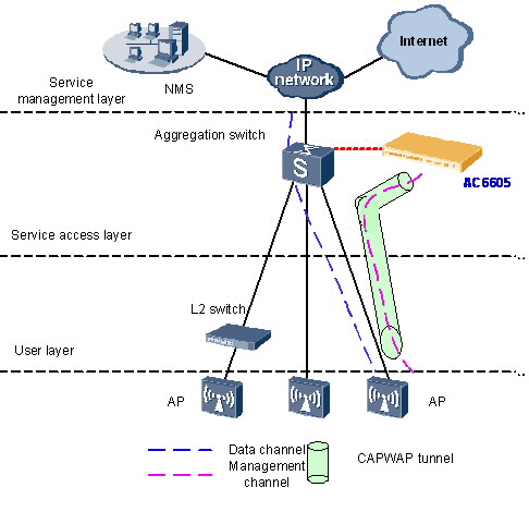
The AC6605 only manages APs. All AP control flows must reach the AC6605.
The aggregation switch has a port to connect to the AC6605 and functions as the DHCP server to allocate IP addresses to APs. APs obtain the IP address of the AC6605 using the DNS function provided by the BRAS or DHCP Option 43 in DHCP packets.
Data flows from APs are forwarded by the Layer 2 switch, aggregation switch, and BRAS and do not pass through the AC6605.
Different VLANs are assigned to STAs with different service set identifiers (SSIDs). The Layer 2 switch and aggregation switch identify packets from these VLANs and forward these packets to the BRAS. The BRAS terminates packets from terminals, controls user access, and allocates IP addresses to users. After a user is authenticated by the BRAS, traffic from the user is forwarded to the Internet across the IP network.
Tunnel Forwarding
In tunnel forwarding mode, wireless user service data is transmitted between APs and ACs over CAPWAP tunnels.
In Figure, both management flows and data flows of APs are transmitted to the AC6605 over CAPWAP tunnels, and then the AC6605 transparently transmits these flows to the upstream device.
Tunnel forwarding is usually used to control wireless user traffic in a centralized manner. This forwarding mode facilitates device deployment and controls all wireless user data flows by aggregating traffic of all wireless users connected to APs to an AC through CAPWAP data tunnels.
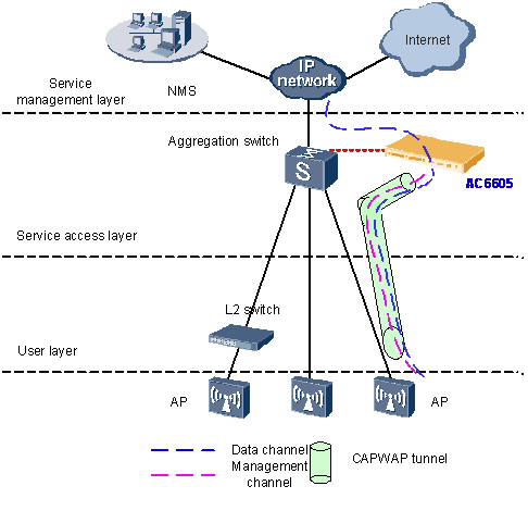
In branched networking mode, the AC6605 manages all the APs connected to the aggregation switch. This network topology applies to scenarios where APs are scattered across hot spots.
The branched networking mode requires only a small modification to the existing network, facilitating device deployment. You can select the direct forwarding or tunnel forwarding mode according to networking requirements. Direct forwarding is recommended to enterprise networks.
Wireless Distribution System
The 802.11 wireless technology has been widely used in home networks and enterprise networks. Users can easily access the Internet over WLANs. In this network application, APs must be connected to the existing wired network to provide network access services for wireless users. To expand the wireless coverage area, APs need to be connected using cables, switches, and power supplies. This increases network costs and prolongs network construction period. The Wireless Distribution System (WDS) allows APs to be connected wirelessly, facilitating WLAN construction in a complex environment.
The WDS is a distribution system comprised of APs. The WDS connects to an AC on the network side, which is then connected to a network device such as a gateway or an aggregation switch. The WDS connects to a station (STA) or PC on the user side.
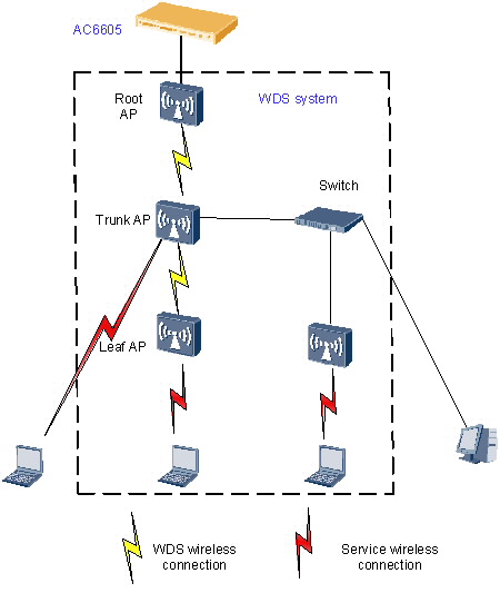
On a WDS network, an AC manages the following devices:
Root AP: connects to an AC on the wired side, and functions as a WDS master to connect to trunk APs or leaf APs.
Trunk AP: functions as a WDS slave to connect to a root AP, connects to wired devices on the wired side, or functions as a WDS master to connect to leaf APs.
Leaf AP: functions as a WDS slave to connect to a root AP or trunk AP or connects to STAs on the wireless side.
The WDS networking can expand WLANs and applies to indoor wireless deployment scenarios.